Industrial networks that transmit data using digital signals often are an integral part of a data acquisition or process control solution. A basic understanding of the network technologies that are available for various applications is required to make the best implementation decisions-decisions that can have a profound effect on the ability to adapt to ever-changing technologies.
The OSI Network Model
Sometimes it helps to understand each layer by examining the technology it represents. The Application Layer is the most intuitive because it is what the user sees. It represents the problem the user wants the system to solve. Internet browsers and e-mail programs are good examples. They allow the user to input and read data while connected between a client PC and a server somewhere on the Internet. In an industrial application, a program on a programmable logic controller (PLC) might control a smart valve.
For example, the type of network(s) or network products selected for a data acquisition application can greatly affect cost/benefit evaluations for future projects. Until recently, fiber optics were an expensive option that seemed like overkill for most applications. But with the information load now likely to flow between nodes on an enterprise network, fiber looks attractive.
Network technologies come in a bewildering array of options, and certain segments of this technology are changing at an incredible rate. The average user might spend weeks researching the various ways to build or improve a network, just to find that once a decision is made and products are purchased, the next wave of bigger, better, faster technology is now available.
A well-designed, integrated solution to data transmission will yield a competitive advantage to any industrial enterprise. Users in all aspects of a business should be able to obtain plant and business data from any physical node, local or remote. "Gluing" pieces of new and/or existing networks together is becoming more feasible with the use of bridging, routing, and media conversion technologies that link local area, wide area, and industrial networks together. And with Internet and wireless technologies, data transmission over large geographic areas is increasingly feasible.
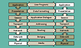
Nearly all digital network descriptions start with the OSI (Open Systems Interconnect) model (Figure 4-1). It explains the various "layers" of network technology. To the casual user, this model is a little abstract, but there is not a better way to begin to understand what is going on.

Figure 4-1: The Seven Layer OSI Network Model
The Presentation Layer performs formatting on the data going to and from the application. This layer performs such services such as encryption, compression, and conversion of data from one form to another. For example, an application (one layer up) might send a time stamp formatted in 12-hour time: 01:30:48 p.m. A more universal representation is 13:30:48, in 24-hour time, which can be accepted or presented at the next node's application in the form that it needs. One advantage to presentation services is that they help eliminate overhead, or embedded services, in application programs.
The Session Layer establishes the connection between applications. It also enforces dialogue rules, which specify the order and speed of data transfer between a sender and a receiver. For example, the session layer would control the flow of data between an application and a printer with a fixed buffer, to avoid buffer overflows. In the time stamp example, once the data is presented in 24-hour time format, an identifier and length indicator are appended to the data string.
The Transport Layer is essentially an interface between the processor and the outside world. It generates addresses for session entities and ensures all blocks or packets of data have been sent or received. In the time stamp example, an address for each session entity (sender and receiver) and checksum are appended to the block generated by the session layer.
The Network Layer performs accounting, addressing, and routing functions on messages received from the transport layer. If the message is lengthy, this layer will break it up and sequence it over the network. This layer also uses a network routing table to find the next node on the way to the destination address. In the time stamp example, a node address and sequence number are appended to the message received from the session layer.
The Data Link Layer establishes and controls the physical path of communication from one node to the next, with error detection. This layer performs media access control (MAC) to decide which node can use the media and when. The rules used to perform these functions also are known as protocols. Ethernet and token ring contention are examples of protocols. In the time stamp example, a header and trailer are appended to the message received from the transport layer for flagging the beginning and end of the frame, type of frame (control or data), checksum, and other functions.
The Physical Layer is perhaps the most conspicuous layer from a cost point of view. It is relatively easy to understand the labor and material costs of pulling cables, along with a physical infrastructure (conduits, raceways, and duct banks) for maintaining cable integrity. This layer does not add anything to the message frame. It simply converts the digital message received from the data link layer into a string of ones and zeroes represented by a signal on the media. One example is RS-485, where a binary 1 is represented by a Mark, or Off state, and a binary 0 is represented by a Space, or On state. A Mark is a negative voltage between terminals on the generator, while a Space is a positive voltage on those terminals.