|
|
 |

Standalone Components
In the previous section, plug-in data acquisition boards for PCs and Macs were examined. In this section, we will look at communications-based, or front-end, data acquisition systems-standalone data acquisition systems that collect data and send it to a processor over a data communications scheme. Data communications involve everything from a simple RS-232 connection to a high-speed network (Chapter 4).
One major advantage of communications-based systems is that they are processor independent. A "box" of standalone data acquisition hardware can transmit its data to a PC, programmable logic controller (PLC), RISC workstation, midrange or mainframe computer, or even the Internet. A standalone system can gather one data point-such as an infrared sensor-or thousands of analog and digital measurement points.
Unlike a plug-in data acquisition system based on a commercial PC, standalone systems often are designed to be located anywhere on the plant floor. Ruggedized I/O modules, racks, power supplies, and sealed NEMA enclosures are readily available to house a data acquisition system, often at a lower cost than a similarly ruggedized industrial computer.
A plug-in data acquisition system is limited by the number of cards that can fit into the available slots of a PC or Mac. Also, when a data acquisition system gets overly large on a PC, it begins to take more and more processor time for DMA access, slowing even the extremely powerful processors. A standalone data acquisition system, on the other hand, can more easily grow to be as large as necessary. You can even start small, building and expanding the system as requirements grow.
Finally, standalone systems are portable from system to system. They operate with industry standard communications, so the I/O can be easily transferred from a PC to a Mac to a PLC as needed.
A plug-in board works with one type of processor only. Even more difficult, all the field wiring terminates at the data acquisition board. To change computers, you may face a monumental rewiring task, even when moving to a bigger and faster computer of the same type.
While a plug-in data acquisition board represents the most efficient and most economical solution to many data acquisition applications, standalone systems have more capability and flexibility. Remember, plug-in boards for PCs and Macs are a relatively new product-they are not more than 15 years old. Standalone systems have been evolving for 35 years or more, since the first supervisory control and data acquisition (SCADA) systems of the 1960s. With hundreds of manufacturers worldwide, and tens of thousands of different devices and models, finding front-end data acquisition equipment to do the job is a much easier task.
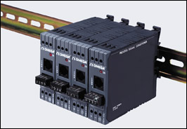 |
Discrete signal conditioners are available to perform almost any
combination of manipulations conceivable. These, for example,
convert raw thermocouple inputs into RS-485 digital signals. |
Connecting to Field I/O
When considering a standalone system, a major question that has to be answered is: How will the field I/O be connected? This involves a choice among several systems: DIN-rail systems, rack-mounted systems, and field-mounted devices.
A DIN-rail system is a convenient way to connect sensor field wiring to signal conditioners, converters, power supplies, terminal blocks, relays, modems, power conditioners, surge suppressors and other devices in the field. The DIN rail is either 32- or 35-mm wide, and provides a sturdy platform on which dozens of devices can be mounted. A single power supply, surge suppressor, and communication module can serve a row of modules.
DIN modules are small, rugged, and designed for high-density installation. For example, high-density signal conditioners from one manufacturer can be packed so close together they can accommodate 52 analog signals in one foot of DIN rail, at a cost of about USD$100 per point. DIN devices often are offered with universal foot mountings that accommodate 32- and 35-mm DIN rails and the Allen-Bradley rail. Adapters are available that allow any flat surface device to mount on a DIN rail. Both schemes allow mixing and matching of I/O devices from several different systems.
Depending on the plant environment, the DIN rails can be mounted in cabinets, racks or NEMA enclosures. Field I/O wiring is brought to the enclosure, and typically connects to termination modules or directly to the signal conditioners.
In most cases, DIN rail devices do not perform any processing of field data other than signal conditioning and conversion. Instead, they serve primarily as a termination and distribution point for field I/O. For data acquisition purposes, DIN devices gather sensor data and distribute it to downstream equipment through RS-232/RS-485 links, various fieldbus or device networks, or other types of communications systems.
Rack-mounted data acquisition systems have been around since the beginning of the industrial control industry. This solution involves I/O modules, subsystems, and processors that are installed in a standard industrial 19-in. rack that's housed in a NEMA free-standing or wall-mounted enclosure. Subsystems and processors typically mount horizontally across the enclosure, while I/O boards and processor cards mount vertically in a card chassis.
The card chassis usually has a built-in power supply for all the I/O and processor cards that plug into it. It may also include a backplane, as in the case of VMEbus and VXIbus, to interconnect the cards and processors. In other systems, a large power supply mounted at the bottom of the enclosure provides conditioned, noise-free power to every module.
Rack-mount systems can accommodate PLC I/O, data-logging systems, remote I/O for a computer, field networks, and just about every type of front-end or I/O on the market today.
Historically, mV sensor signals have been wired to a transmitter or transducer that converts the signal into a higher voltage or a 4-20 mA current loop signal that is less susceptible to electrical interference (see Chapter 3). While this is still a perfectly acceptable technique, newer field-mounted devices are becoming available. One of the hottest topics in I/O today is the digital instrument network, which involves connecting sensors to data acquisition systems or host computers via a digital signal (see Chapter 4). Field-mounted transmitters of yesterday have become extremely powerful digital devices that do much more than convert data. "Smart" transmitters and I/O devices can now mount at or near the sensor location in junction boxes or sealed enclosures, and perform a wide variety of signal conditioning and processing functions locally.
Signal Conditioners
Signal conditioners are available to handle virtually every sensor on the market today, including mV, V, mA, and resistance signals from RTD, thermocouple, potentiometer, strain gage, load cell, LVDTs, and frequency sensors, to name the most common.
In many cases, the signal conditioning consists of signal isolation, filtering, amplification, and linear conversion of signals ranging from ±10 mV to ±40 V to a more usable voltage.
For thermocouple inputs, signal conditioners linearize the incoming signal and perform cold junction compensation to increase accuracy. A thermocouple signal conditioner usually accepts inputs from types J, K, T, E, R, S, B, and N thermocouples. RTDs may be 2- or 3-wire. For sensors that require an excitation voltage, such as a strain gage or load cell, the signal conditioner supplies it.
DIN-rail signal conditioners are narrow devices that often accommodate only one signal at a time and have a selectable output from 0-5 V or ±10 V, 4-20 or 0-20 mA, and RS-232 or RS-485 communications. With RS-485, up to 32 modules can be connected to a single computer communications port.
Signal conditioners in rack systems are full-size I/O boards that plug into the chassis. Sensor signals terminate at the I/O board or onto terminal panels. A typical analog input board accepts 8, 16, or 32 channels. Unlike multifunction PC boards, rack systems tend to specialize. For example, all digital I/O goes to a digital I/O card, thermocouples go to a thermocouple input board, and so on.
Field-mounted signal conditioners have the same capabilities as DIN-rail and rack-mount devices, but are packaged in tougher enclosures. Some are in "hockey puck" packages, others in I/O "bricks." Both can be mounted near the sensor in benign environments, or housed in junction boxes or small enclosures if the environment is more difficult.
Transmitters
A traditional analog transmitter takes a sensor signal, amplifies and conditions it, and sends it on its way as a 4-20 mA signal that is relatively noise immune and intrinsically safe if necessary. In a two-wire system, power for the transmitter's electronics is taken from the current loop. In a four-wire transmitter, power is provided from an external source on a second set of wires.
As you might expect, today's technology has gone far beyond this point. Many of today's transmitters are ŇsmartÓ devices that communicate to a host PC or PLC via a digital signal superimposed on the 4-20 mA current, or by RS-232, RS-485, or other digital networks (Chapter 4). Embedded microprocessors perform diagnostics and self-calibration, and accept programming and setpoint information from a host processor. Smart transmitters also can be configured remotely for any number of tasks, thereby cutting down on the number of different transmitters needed for spares. Power for the transmitter is supplied by the 4-20 mA current loop, the phone line in a modem-equipped device, or by the RS-232 line.
Some smart transmitters accept two sensor inputs, using one as the primary and the other as a hot backup. If the primary sensor fails, the transmitter switches over instantly and notifies the host. More and more system responsibility is being off-loaded to smart transmitters. In one system, the transmitter does not send data at all, unless it has changed from the previous value. In another, outputs from three transmitters are evaluated by a two-out-of-three voting scheme to determine which one has seen a false input (for example, flame-out in a flare stack application).
Alarm Modules
With computer processors available at all levels of a data acquisition system, the need for alarm modules has diminished. When independent local alarm indication is needed, however, alarm modules are an ideal solution.
DIN-rail mounted alarm modules typically accept an ac or dc voltage or current input signal, or a temperature reading from a thermocouple or RTD, and compare the input with high and low setpoints. The limit alarm can be field configured for high or low, fail-safe or non-fail-safe operation.
Alarm modules have one or more relay outputs for sounding audible alarms or illuminating a panel annunciator. When the operator investigates, the alarm module has LED indicators that show input status.
Remote I/O
Many PLCs and computer-based control systems use remote I/O to collect data in a far-off location, from a work cell where sensors are concentrated, or from various convenient locations in a plant. The remote I/O system serves as a data concentrator, minimizing the amount of physical cabling needed to directly connect each field I/O point.
In some cases, the I/O for a PLC is assembled into a cabinet by the vendor-complete with analog and digital I/O, termination cards, signal conditioners, and other devices. The remote system communicates with its host over a communications network.
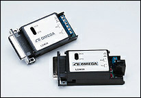 |
General purpose modems are a low cost
option for sending digital information at
rates up to 57.6 kbps. |
Computer-based control systems can use remote I/O made up from digital and analog I/O boards from a wide variety of vendors, sent over any of several data communications schemes. In many cases, a large control system spread over a plant floor may be taking data from entirely different types of data acquisition equipment. Information coming from a testing lab might be originating in analyzers and instruments that use the IEEE-488 standard; real-time data from a batch reactor may consist of dozens of 4-20 mA flow, pressure, and temperature transmitter signals coming in over a fieldbus network; and information from the inventory control material-handling system could be motion control data from resolvers, encoders, and limit switches gathered by a PLC and made available on a PLC communications network.
Front end: A front end is simply a dedicated I/O system that is set apart from the host computer or controller. The two systems are physically separated, with all or most of the I/O concentrated in the front end. A front end typically connects to the computer via one or more parallel cables that support a 32- or 64-bit interface. The front end may connect to multiple remote I/O units, networks, serial I/O, or PLC data highways.
|