|
|
 |

Noise & Grounding
In transmitting analog signals across a process plant or factory floor, one of the most critical requirements is the protection of data integrity. However, when a data acquisition system is transmitting low level analog signals over wires, some signal degradation is unavoidable and will occur due to noise and electrical interference. Noise and signal degradation are two basic problems in analog signal transmission.
Noise is defined as any unwanted electrical or magnetic phenomena that corrupt a message signal. Noise can be categorized into two broad categories based on the source-internal noise and external noise. While internal noise is generated by components associated with the signal itself, external noise results when natural or man-made electrical or magnetic phenomena influence the signal as it is being transmitted. Noise limits the ability to correctly identify the sent message and therefore limits information transfer.
Some of the sources of internal and external noise include:
Electromagnetic interference (EMI);
Radio-frequency interference (RFI);
Leakage paths at the input terminals;
Turbulent signals from other instruments;
Electrical charge pickup from power sources;
Switching of high-current loads in nearby wiring;
Self-heating due to resistance changes;
Arcs;
Lightning bolts;
Electrical motors;
High-frequency transients and pulses passing into the equipment;
Improper wiring and installation;
Signal conversion error; and
Uncontrollable process disturbances.
Signal leads can pick up two types of external noise-common mode and normal mode. Normal mode noise enters the signal path as a differential voltage and cannot be distinguished from the transducer signal. Noise picked up on both leads from ground is referred to as common-mode interference.
 |
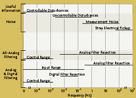
| Figure 3-3:Signal, Noise, and Filtering Frequencies |
Typical ranges for data signals and noise are shown in Figure 3-3. Whether the noise is detrimental to the proper performance of the system depends on the ratio of the total signal power to the total noise level. This is referred to as the signal-to-noise ratio. If the signal power is large in comparison to the noise signal, the noise can often times be ignored. However, with long-distance signals operating with limited signal power, the noise may disrupt the signal completely.
Current-driven devices have been most widely accepted in processing plants, with a common current range of 4-20 mA. Low-level current signals are not only safe, but are not as susceptible to noise as voltage signals. If a current is magnetically coupled into the connecting wires in the transmission of the signal from a current source, no significant change in the signal current will result. If the transducer is a voltage-driven device, the error adds directly to the signal. After current transmission, voltage signals can be easily rederived.
Even though internal and external interference can be problematic in sending analog signals, analog signal transmission is widely and successfully used in industry. The effects of noise can be reduced with careful engineering design, proper installation, routing techniques of wires and cables, and shielding and grounding.
One of the ways in which engineers have tried to minimize the effects of noise is to maximize the signal-to-noise ratio. This involves increasing the power of the signal being sent. Although this works in some cases, it has its limitations. By increasing the signal, nonlinear effects become dominant, as the signal amplitude is increased-it enhances the signal and the noise in the same proportion.
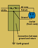
Proper grounding also is essential for effective operation of any measurement system. Improper grounding can lead to potentially dangerous ground loops and susceptibility to interference. To understand the principles involved in shielding and grounding, some terms must first be understood. A ground is a conducting flow path for current between an electric circuit and the earth. Ground wires are typically made with materials that have very low resistance. Because current takes the path of least resistance, the ground wires connected from the system provide a stable reference for making voltage measurements. Ground wires also safeguard against unwanted common-mode signals and prevent accidental contact with dangerous voltages. Return lines carry power or signal currents (Figure 3-4). A ground loop is a potentially dangerous loop formed when two or more points in an electrical system are grounded to different potentials.
 |
Figure 3-4:A Ground
Conductor |
There are many different grounding techniques designed to not only protect the data being transmitted, but to protect employees and equipment. There are two ways in which all systems should be grounded. First of all, all of the measuring equipment and recording systems should be grounded so that measurements can be taken with respect to a zero voltage potential. This not only ensures that potential is not being introduced at the measuring device, but ensures that enclosures or cabinets around equipment do not carry a voltage. To ground an enclosure or cabinet, one or more heavy copper conductors are run from the device to a stable ground rod or a designated ground grid. This system ground provides a base for rejecting common-mode noise signals. It is very important that this ground is kept stable.
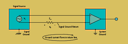
The second ground is for the signal ground. This ground is necessary to provide a solid reference for the measurement of all low-level signals. It is very important that this ground is grounded separate and isolated from the system ground. If a signal return line is grounded at the signal source and at the system ground, a difference in potential between the two grounds may cause a circulating current (Figure 3-5). In this case, the circulating current will be in series with the signal leads and will add directly to the signal from the measuring instrument. These ground loops are capable of creating noise signals 100 times the size of the original signal. This current can also be potentially dangerous. In a single-point ground configuration, minimal current can flow in the ground reference. Figure 3-6 shows that by grounding the wire at the signal end only, the current has no path, eliminating the ground loop.
 |
| Figure 3-5:Incorrect Grounding of Signal Circuit |
For off-ground measurements, the shield or the ground lead is stabilized with respect to either the low-level of the signal or at a point between the two. Because the shield is at a potential above the zero-reference ground, it is necessary to have proper insulation.
|


