|
|
 |

Vessel Stabilization
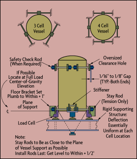
To provide unrestricted vertical motion while allowing for horizontal thermal expansion, stay rods and check rods are used. They are made from threaded rods and nuts and serve to provide lateral restraint. Their nuts are adjusted snug to the gusset of the vessel support bracket and to a rigid bracket on the structure. Nuts should be finger tight and then secured with jam nuts (Figure 8-1).
 |
| Figure 8-1: Tank Staying Arrangement
|
Rods must be level and installed perpendicular to the direction of thermal expansion of the vessel. This allows unrestricted vertical movement without producing a side load. Stay rods should be installed as close as possible to the plane of vessel support. On long, round, horizontal tanks, the axial vessel stay rod connection should be near the center of the vessel, and lateral restraints should be located near the ends. This helps to avoid large axial thermal expansion.
Check rods are identical to stay rods except that their fit is made loose by providing a 1/8-in. gap at the nut and oversized rod holes. Check rods may be mounted above or below the support plane or vertically to prevent vessel overturn. On suspended vessels, check rods also serve as back-up hangers.
To determine the required size and location for stabilization systems, external forces (seismic, agitator, etc.) must be evaluated. The most stable support plane is at the center of gravity of the tank when it is full. Suspended vessels require check or stay rods only when horizontal vessel movement can be caused by external forces. For minor forces, bumpers may be sufficient.
 |
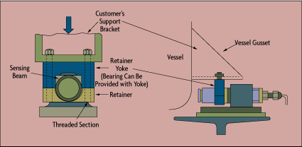
| Figure 8-2: Cantilever Load Cells Reduce Staying Requirements
|
Thermal expansion of vessels relative to their supports can cause undesirable side loads on the load cells. Some load-cell designs provide for horizontal vessel movement to relieve side loading. Load cell rods suspending a vessel must remain plumb to within 0.5*. Single and double-ended shear beam cell designs can eliminate or minimize the need for stay or check rods (Figure 8-2), while cylindrical cells always require both.
In terms of allowing horizontal movement, load cell designs can be "fixed" (allowing no movement), "linear" (allowing linear movement), or "full" (allowing any horizontal tank movement). Fixed and linear cells are mounted in support positions that are farthest apart, with the linear movement being allowed in a line that intersects the fixed cell.
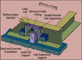
Load cell adaptors are used in vehicle scales where large horizontal forces occur due to the deceleration or acceleration of the vehicles on the scale. The adaptor suspends the weighing platform from the top of the load cell through swivel links connected to the lower plate and the platform. The load cell is supported by a base plate that absorbs heavy side loads when the horizontal deflection exceeds the clearances around the base plate. Similar designs are available for double-ended shear beams (Figure 8-3).
 |
| Figure 8-3: End-Loaded Shear-Beam Installation
|
Piping Connections
If a pipe is attached to a weighed vessel, it will introduce vertical and horizontal forces. The total vertical force (V) generated by all piping connected to a weighed vessel should be less than 30 times the system accuracy (A) multiplied by the maximum live load (L):

The forces imposed by the pipe supports, the pipe, and the pipe contents--plus the spring forces resulting from pipe movement due to thermal expansion--must all be included in V, and in the evaluation of horizontal forces. The horizontal forces acting on the vessel should be zero.
Following are some general rules to assist in obtaining an acceptable design:
Piping must align with the vessel connection without requiring any force.
The length of pipe between the vessel and the first pipe support should be long enough to provide vertical flexure, but not so long that the pipe will sag and add weight to the vessel.
Load cell supports should also support the first two pipe supports. The up and down motion of the pipe supports must be limited.
When possible, use a lighter schedule pipe because it will provide more flexibility. For example, schedule 10S is more flexible than 40S.
The transmission of horizontal forces should be eliminated by the use of expansion joints and by piping designs having 90* turns in two planes.
Flexible fittings, universal joints, and hose may only be used when making horizontal connections and must align normal to the tank connection, without force. Braid-jacketed hose should not be used. Flexible rubber boots are acceptable for making vertical connections.
When a hopper and its hood are independently supported and sealed with a boot, weighing error can occur due to the pressure change caused by in-rushing or out-flowing material. Hood venting (and, therefore, vacuum breaking) is required to eliminate this error source.
Hose should not be used to make turns.
Do not use rigid insulation on flexible joints.
On horizontal round tanks, the best location for the pipe entrance is near the "fixed" load cell.
The electrical devices on the tank (including load cells) should be wired using flexible conduit that is "looped."
|


![]()