Measurement Limitations
In the case of "gauge" pressure measurement, the reference is atmospheric pressure, which is itself variable (Figure 1-3). Thus, sensor output can change not because there is a change in the process pressure, but because the reference pressure is changing. The barometric pressure can change by as much as an inch of mercury (13.6 inches of water), which in some compound measurements can result in excessive and intolerable errors. By definition, a compound pressure detector measures near atmospheric pressures, both above and below atmospheric.
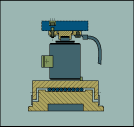
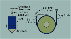
It is equally important to protect and isolate the load cells from horizontal forces. These forces can be caused by thermal expansion or by the acceleration and deceleration of vehicles on active weighing platforms. Therefore, it is essential that load cells be either free to move in the horizontal (Figure 1-5) or be provided with an adaptor that transmits virtually no side load. In addition, tanks--particularly agitated reactors--should be stayed, that is, protected from rotary motion. This is achieved by installing three stay rods, each with two ball joints (Figure 1-6).
One of the basic limitations of all measurement science, or metrology, is that all measurements are relative. Therefore, all sensors contain a reference point against which the quantity to be measured must be compared. The steelyard was one of mankind's first relative sensors, invented to measure the weight of an object (Figure 1-1). It is a beam supported from hooks (A or B), while the object to be weighed is attached to the shorter arm of the lever and a counterpoise is moved along the longer arm until balance is established. The precision of such weight scales depends on the precision of the reference weight (the counterpoise) and the accuracy with which it is positioned.
Similarly, errors in pressure measurement are as often caused by inaccurate reference pressures as they are by sensor inaccuracies. If absolute pressure is to be detected, the reference pressure (theoretically) should be zero--a complete vacuum. In reality, a reference chamber cannot be evacuated to absolute zero (Figure 1-2), but only to a few thousandths of a millimeter of mercury (torr). This means that a nonzero quantity is used as a zero reference. Therefore, the higher that reference pressure, the greater the resulting error. Another source of error in absolute pressure measurement is the loss of the vacuum reference due to the intrusion of air.

Figure 1-5: Typical Load
Cell Installation
Consider, for example, a blanketed chemical reactor. A typical case is a reactor which (when empty) needs to be evacuated to an absolute pressure of 10 torr. After evacuation, it must be purged with an inert gas, while the pressure in the reactor is maintained at 1 in. of water above atmospheric. No pressure sensor provided with a single reference is capable of detecting both of these pressures. If a vacuum reference is used, the purge setting of 1 in. water cannot be maintained, because the instrument does not know what the barometric pressure is. On the other hand, if a barometric reference is used, the 10-torr vacuum cannot be measured because the reference can change by more than the total value of the measurement--as much as 25 torr.
Today, with microprocessors, it would be possible to provide the same pressure sensor with two references and allow the intelligence of the unit to decide which reference should be used for a particular measurement.
Another important consideration in force-related measurements is the elimination of all force components which are unrelated to the measurement. For example, if the goal is to measure the weight of the contents of a tank or reactor, it is essential to install the vessel in such a way that the tank will behave as a free body in the vertical but will be rigidly held and protected from horizontal or rotary movement. This is much more easily said than done.
Freedom for the vessel to move in the vertical direction is achieved if the tank is supported by nothing but the load cells. (The amount of vertical deflection in modern load cells is less than 0.01 in.) This means that all pipes, electrical conduits, and stay rods connected to the vessel must be designed to offer no resistance to vertical movement. In pressurized reactors, this usually requires the use of flexible piping connections installed in the horizontal plane (Figure 1-4) and ball joints in the stay rods. For best results in larger pipes, two horizontal flexible couplings are typically installed in series.

Figure 1-6: Tank "Staying" Designs
The art of weighing requires a lot of common sense. A successful weighing system requires that tank supports be rigid and be located above the vessel's center of gravity for stability. This is particularly important outdoors, where outside forces such as the wind need to be considered. It is also important that the load be evenly distributed among the load cells. This consideration necessitates that all load buttons be positioned in the same plane. Since three points define a plane, equal load distribution is easiest to achieve by using three load cells.
Common sense also tells us that the accuracy of an installation will not match the precision of the load cells (which is usually 0.02% or better) if the full load is not being measured or if the load cells are not properly calibrated. The precision of high quality load cells does little good if they are calibrated against flowmeters with errors of 1% or more. The only way to take full advantage of the remarkable capabilities of accurate modern load cells is to zero and calibrate the system using precision dead weights. It is also important to remember that dead weights can only be attached to a reactor if hooks or platforms are provided for them.
Range considerations also are important because load cells are percent-of-full-scale devices. This means that the absolute error corresponding to, say, 0.02% is a function of the total weight being measured. If the total weight is 100,000 pounds, the absolute error is 20 pounds. But if one needs to charge a batch of 100 pounds of catalyst into that same reactor, the error will be 20%, not 0.02%.
| References & Further Reading | |
| Black Holes and Baby Universes and Other Essays, Stephen Hawking, Bantam Books, 1993. | |
| Instrument Engineers' Handbook, Bela Liptak, CRC Press LLC, 1995. | |
| Instrumentation Reference Book, 2nd Edition, B.E. Noltingk, Butterworth-Heinemann, 1995. | |
| Marks' Standard Handbook for Mechanical Engineers, 10th Edition, Eugene A. Avallone and Theodore Baumeister, McGraw-Hill, 1996. | |
| McGraw-Hill Concise Encyclopedia of Science and Technology, McGraw-Hill, 1998. | |
| >Perry's Chemical Engineers' Handbook, 7th Edition, Robert H. Perry, Don W. Green, and James O. Maloney, McGraw-Hill, 1997. | |
| Process Control Systems: Application, Design, and Tuning, 4th Edition,F. Greg Shinskey, McGraw Hill, 1996. | |
| Van Nostrand's Scientific Encyclopedia, Douglas M. Considine and Glenn D. Considine, Van Nostrand, 1997. |