Cookies del sito web Omega Utilizziamo i cookies nel nostro sito web. Questi cookies sono necessari per consentire al sito web di funzionare correttamente. Se si continua senza modificare la propria configurazione del browser, si acconsente a ricevere i cookies dal nostro sito web. Per maggiori chiarimenti sull'utilizzo dei cookies, cliccare qui
Click on this link if you need more information about Data Acquisition .
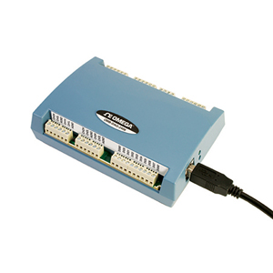
The USB data acquisition module of the OMB-DAQ-2408 Series are designed
for highly-accurate voltage or
temperature measurements. Each
device features up to 16 single
ended (SE)/8 differential (DIFF)
analog inputs. Each device includes
8 digital I/O and two counter inputs.
The OMB-DAQ-2408-2AO also
features two analog outputs. Each
device in the series offers 24-bit
resolution for ultra-accurate voltage
or thermocouple measurements.
Analog Input
Each device includes 16 SE/8 DIFF
analog inputs which you can
configure for voltage or thermocouple
input on a per-channel basis. Eight
software-selectable voltage input
ranges are provided. You can
configure these ranges on a
per-channel basis from ±10V to
±0.078V. When measuring
thermocouples, configure analog
inputs in DIFF mode. All devices also
include open thermocouple detection
to identify improperly working
thermocouples.
Sample Rate
OMB-DAQ-2408 modules can sample
analog input channels at up to 1 kS/s.
Digital I/O
Eight digital I/O channels are included with each OMB-DAQ-2408
and you can read from or write to each individual bit.
Counters
Two 32-bit counters are included with OMB-DAQ-2408 modules. The
TTL level inputs are capable of read/write rates of up to 500 Hz and
an input frequency of up to 1 MHz.
Analog Output
(OMB-DAQ-2408-2AO Only)
The OMB-DAQ-2408-2AO includes two 16-bit analog outputs. Each
output has a ±10V range. Both outputs can be updated at a rate of
up to 500 S/s per channel; one output can be updated at a rate of 1 kS/s.
Software
The OMB-DAQ-2408 modules ship with an impressive array of software, including the new TracerDAQ®, a full-featured, out-of-the-box data logging, viewing, and analysis application. Driver support and detailed example programs are included for Universal Library programming
libraries for Microsoft® Visual Studio® programming languages, and other
languages, including DASYLab®, and ULx for NI LabVIEW® (comprehensive
library of VIs and example programs compatible with 32-bit and 64-bit
LabVIEW v8.5 through 2012) and InstaCalTM installation, calibration
and test utility-powerful solutions for programmers and nonprogrammers
alike. These modules operate under Microsoft Windows® XP (32-bit only) and VISTA/7/8 (32-bit and 64-bit) operating systems.
Specifications
ANALOG INPUT
A/D Converter Type: ADS1256,
24-bit Sigma Delta A/D Data Rates: 3750 S/s, 2000 S/s,
1000 S/s, 500 S/s, 100 S/s,
60 S/s, 50 S/s, 25 S/s, 10 S/s, 5 S/s, 2.5 S/s Throughput (Software-Selectable
for Single Channel and Multiple Channels)
Single Channel: 2.5 to 1102.94 S/s Multiple Channels: 0.16 to 1102.94 Hz Number of Channels: Up to 16
channels individually software-selectable
as single ended (SE) or differential (DIFF); thermocouples
require differential mode;
for each channel configured as differential,
you lose one single-ended channel Input Isolation: 500 Vdc min between
field wiring and USB interface Channel Configurations:
Temperature sensor input,
software-selectable to match sensor type; voltage input Input Voltage Range
Thermocouple Mode: ±0.078125V Voltage Mode (Software-Selectable):
±10V, ±5V, ±2.5V, ±1.25V, ±0.625V,
±0.3125V, ±0.15625V, ±0.078125V Absolute Maximum Input Voltage
CxH-CxL Relative to GND:
±22V max (power on), ±10V max (power off) Input Impedance: 10 MΩ (power on), 390 Ω (power off) Input Leakage Current: ±20 nA Input Voltage: >±22V (power on/off): ±1µ A max Input Capacitance: 590 pf Maximum Working Voltage (Signal + Common Mode)
Voltage Mode: ±10.25V max Common Mode Rejection Ratio
Thermocouple Mode (fIN = 60 Hz): 110 dB Voltage Mode (fIN = 60 Hz, All Input Ranges): 90 dB ADC Resolution: 24-bits Crosstalk: Adjacent channels, 100 dB Input Coupling: DC Channel Gain Queue: Up to 64
elements, software-selectable channel and range Warm-Up Time: 45 minutes min Open Thermocouple Detect:
Software-selectable for each channel CJC Sensor Accuracy 15 to 35°C: ±0.5°C typ 0 to 55°C: ±1.0°C max
THROUGHPUT RATE
The maximum throughput of an OMB-DAQ-2408 module is 1.1 kS/s
aggregate. The OMB-DAQ-2408 provides the ability to set conversion
rates on a per-channel basis. This feature gives the user flexibility
and control over noise averaging for each channel.
ANALOG VOLTAGE OUTPUT
(OMB-DAQ-2408-2AO ONLY)
Digital to Analog Converter: DAC8552 Number of Channels: 2 Resolution: 16-bits Output Ranges Calibrated: ±10 V Uncalibrated: ±10.05V, software-selectable Output Transient
Host computer is reset, powered on, suspended or a reset command
is issued to device Duration: 2 s Amplitude: 2V p-p Initial Power On Duration: 50 ms Amplitude: 5V peak Differential Non Linearity: ±0.25 LSB typ, ±1 LSB max Output Current: AOUTx pins, ±5.0 mA max Power On and Reset State: DACs cleared to zero-scale, 0V,
±50 mV Settling Time: To rated accuracy, 10V step, 75 µs Slew Rate: 1.0 V/µ Throughput Single-Channel: 1000 S/s max, system-dependent Multi-Channel: 1000 S/s /#ch max, system-dependent Calibrated Absolute Accuracy Range: ±10V Accuracy (±LSB): 16.0
DIGITAL INPUT Number of I/O: 8 channels Configuration: Each DIO bit can be independently read from (DIN)
or written to (DOUT). DIN bits can be read at any time whether the
DOUT is active or tri-stated. Input Voltage Range: 0 to 15V Input Type: CMOS (Schmitt trigger) Input Characteristics:
47 kΩ pull-up/pull-down resistor, 28 Ω series resistor Maximum Input Voltage Range:
0 to 20V max (power on/off, relative to DGND) Pull-Up/Pull-Down Configuration:
All pins pulled up to 5V through individual 47 kΩ resistors (the J6
shorting block default position is pins 1 and 2) Pull-down capability is
available by placing the J6 shorting block across pins 2 and 3 Transfer Rate (Software Paced):
500 port reads or single bit reads per second typ Input High Voltage: 1.3 to 2.2V Input Low Voltage: 1.5 to 0.6V Schmitt Trigger Hysteresis: 0.4V to 1.2
DIGITAL OUTPUT
Number of I/O: 8 channels Configuration: Each DIO bit can be independently read from (DIN) or
written to (DOUT). DIN bits can be read at any time whether the DOUT
is active or tri-stated. Output Characteristics: 47 kΩ pull-up, open drain (DMOS transistor) internally connected to DGND Pull-Up Configuration: All pins pulled up to 5V through individual
47 kΩ resistors (the J6 shorting block default position is pins 1 and
2). Transfer Rate (Software Paced) Digital Output:
500 port writes or single bit writes per second typ Output Voltage Range: 0 to 5V (no external pull up resistor, internal
47 kΩ pull-up resistors connected to 5V by default); 0 to 15V max Drain to Source Breakdown Voltage: 50V min Off State Leakage Current: 1.0 µA Sink Current Capability: 150 mA max (continuous) per output pin
150 mA max (continuous) for all eight channels DMOS Transistor On-Resistance (Drain to Source): 4 Ω
COUNTER
Pin Names: CTR0, CTR1 Number of Channels: 2 channels Resolution: 32-bits Counter Type: Event counter Input Type: Schmitt trigger, rising edge triggered Input Source: CTR0 (pin 44), CTR1 (pin 42) Counter Read/Writes Rates (Software Paced) Counter Read: System dependent, 500 reads per second. Counter Write: System dependent, 500 writes per second. Input Characteristics: Each CTRx input pin has 562 kΩ
resistor pulled up to 5V and a 10 kΩ series resistor Input Voltage Range: ±15V max Maximum Input Voltage Range:
CTR0, CTR1 relative to GND and DGND, ±20V max (power on/off) Input High Voltage: 1.3 to 2.2V Input Low Voltage: 1.5 to 0.6V Schmitt Trigger Hysteresis: 0.4 to 1.2V Input Bandwidth (-3 dB): 1 MHz Input Capacitance: 25 pf Input Leakage Current: ±120 nA @5V, ±1.6 mA @±15V Input Frequency: 1 MHz, max High Pulse Width: 500 ns, min Low Pulse Width: 500 ns, min
MEMORY
EEPROM: 4096 bytes isolated
micro reserved for sensor configuration,
256 bytes USB micro for external application use
MICROCONTROLLER
Type: One high-performance 8-bit
RISC microcontroller with USB interface (non-isolated);
one high-performance 16-bit RISC microcontroller for measurements
(isolated)
POWER
Supply Current: Quiescent current, 275 mA (includes
up to 10 mA for the status LED; does not include
any potential loading of the digital I/O bits, 5V user terminal or the
AOUTx outputs). 5V User Output Voltage Range:
Available at terminal block pin 40, 4.75 to 5.25V 5V User Output Current: Available
at terminal block pin 40, 10 mA max Isolation: Measurement system to PC, 500 Vdc min
USB SPECIFICATIONS
USB Device Type: USB 2.0 (full-speed) USB Cable Length: 3 m (9.8') max
ENVIRONMENTAL
Operating Temperature Range:
0 to 50°C (32 to 12°F) Storage Temperature Range:
-40 to 85°C (40 to 185°F) Humidity: 0 to 90% RH non-condensing
MECHANICAL
Dimensions: 127 L × 89.9 W × 35.6 mm D
(5.00 × 3.53 × 1.40") Weight: 160 g (5.6 oz)