Cookies del sito web Omega Utilizziamo i cookies nel nostro sito web. Questi cookies sono necessari per consentire al sito web di funzionare correttamente. Se si continua senza modificare la propria configurazione del browser, si acconsente a ricevere i cookies dal nostro sito web. Per maggiori chiarimenti sull'utilizzo dei cookies, cliccare qui
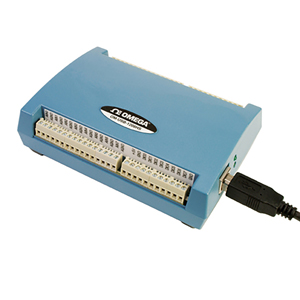
The OM-USB-1208HS, OM-USB-1208HS-2AO
and OM-USB-1208HS-4AO are USB 2.0 full-speed voltage input
data acquisition modules (fully compatible with both USB 1.1
and USB 2.0 ports). These are stand-alone plug-and-play modules
which draw power from the USB cable– no external power supply
is required. All configurable options (including individual channel
ranges) are software programmable, and the modules
are fully software calibrated. All three OM-USB-1208HS modules
provide 13-bit resolution, and 4 differential or 8 single-ended analog
inputs. These modules support software programmable ranges from
±5 to ±20V in a differential configuration, and ±2.5 to ±10V,
and 0 to 10V in a single-ended configuration. In software-paced
mode, these modules can sample at a maximum of 4 kS/s. In hardwarepaced
mode, they can sample at a maximum of 1 MS/s.
The OM-USB-1208HS-2AO provides two 12-bit analog outputs,
and the USB-1208HS-4AO provides four 12-bit analog outputs.
Both modules offer an output range of ±10V. Analog outputs update at a
maximum rate of 5 kS/s in softwarepaced mode; in hardware-paced
mode, each analog output updates at a maximum rate of 1 MS/s.
On these modules, 16 digital I/O can be programmed on each individual
bit as either inputs or outputs. Each module supports two 32-bit TTL-level
counters that accept frequency inputs of up to 20 MHz.
The packaging for the OM-USB-1208HS,
OM-USB-1208HS-2AO and OM-USB-1208HS-4AO
ensures ease of use in a variety of applications. The modules
can easily be DIN-rail mounted for rack applications.
The OM-USB-1208HS, OM-USB-1208HS-2AO
and OM-USB-1208HS-4AO modules ship with an impressive array of software, including the new TracerDAQ®, a full-featured, out-of-the-box data logging, viewing, and analysis application. Driver support and detailed example programs are included for Universal Library programming
libraries for Microsoft® Visual Studio® programming languages, and other
languages, including DASYLab®, and ULx for NI LabVIEW® (comprehensive
library of VIs and example programs compatible with 32-bit and 64-bit
LabVIEW v8.5 through 2012) and InstaCalTM installation, calibration
and test utility-powerful solutions for programmers and nonprogrammers
alike. These modules operate under Microsoft Windows® XP (32-bit only) and VISTA/7/8 (32-bit and 64-bit) operating systems.
The OM-USB-1208HS, OM-USB-1208HS-2AO
and OM-USB-1208HS-4AO data acquisition modules are supplied
with TracerDAQ software which is a collection of four virtual
instrument applications used to graphically display and store input
data and generate output signals:
• Strip Chart—Log and graph values acquire from analog inputs,
digital inputs, temperature inputs and counter inputs • Oscilloscope—Display values acquired from analog inputs • Function Generator—Generate waveforms for analog outputs • Rate Generator—Generate waveforms for counter outputs
TracerDAQ PRO is an enhanced version of TracerDAQ. A
comparison of some of the feature included in TracerDAQ vs TracerDQ
PRO is shown on the PDF.
SPECIFICATIONS
ANALOG INPUT
A/D Converter: Successive approximation type Input Ranges: Software selectable per channel Differential: ±20V, ±10V, ±5V (the voltage level on each
individual AIN input is limited to ±14V) Single Ended: ±10V, ±5V, ±2.5V, 0 to 10V Number of Channels:
4 differential/8 single-ended (software-selectable) Input Configuration: Multiplexed Channel Gain Queue: 8 unique consecutive elements,
software-configurable range for each channel Absolute Maximum Input Voltage: CHx IN to GND Power On: ±25V max Power Off: ±12V max Input Impedance: 35 MΩ min. Input Bandwidth (-3 dB): All input ranges, 2 MHz typ Input Leakage Current: ±250 nA typ Input Capacitance: 32 pf typ Maximum Working Voltage: (Signal + Common Mode)
±20V: ±14V, ±10V: ±11V, ±5V: ±5.5V Sampling Rate: 1 S/s to 1 MS/s, software programmable Sample Clock Source: Internal A/D clock or AICKI Burst Mode: Software-selectable, burst rate = 1 µs Throughput
Software-Paced: 33 to 4000 S/s typ, system-dependent Hardware-Paced: 1 MS/s max
Resolution: 13-bits A/D No Missing Codes (Uncalibrated)
Differential (Mode): 13-bits Single Ended (Mode): 12-bits CMRR: 60 Hz, 74 dB typ
ANALOG OUTPUT
D/A Converter: Texas Instruments DAC7553 Number of Channels: 4 independent Resolution: 12-bits Output Range Calibrated: ±10V Uncalibrated: ±10.2V D/A Update Rate Software Paced: 33 to 5000 S/s typ, system dependent Hardware Paced: 1 MHz max (per channel) Sample Clock Source: Internal D/A clock or AOCKI (AO external clock
input pin) Monotonicity: 12-bits Output Current: ±3 mA max per channel Power Up and Reset State: 0V Output Noise: 0.53 mV rms Absolute Accuracy: ±0.1% Slew Rate: 6.7V/µs typ
DIGITAL I/O Digital Type: CMOS Number of I/O: 16 Configuration: Each bit may be configured as input
(power on default) or output Pull-Up Configuration: The port has 47 kΩ resistors configurable as
pull-ups or pull-downs by an internal jumper (default setting is pull-down) Digital I/O Transfer Rate (System Paced): 33 to 8000 port
reads/writes or single-bit reads/writes per second typ,
system dependent. Input High Voltage: 2.0V min, 5.5V absolute max Input Low Voltage: 0.8V max, -0.5V absolute min, 0V recommended min Output High Voltage: 4.4V min
(IOH = -50 µA), 3.76V min
(IOH = -24 mA) Output Low Voltage: 0.1V max
(IOL = 50 µA), 0.44V max
(IOL = 24 mA) Output Current: ±24 mA max per terminal
EXTERNAL TRIGGER Trigger Source: TRIG input Trigger Mode: Software configurable for edge- or level-sensitive,
rising or falling edge, high or low level. Power on default
is edge sensitive, rising edge. Trigger Latency: 1 µs + 1 clock cycle max Trigger Pulse Width: 100 ns min Input Type: Schmitt trigger, 33 Ω series resistor and 47 kΩ pull-down to ground Schmitt Trigger Hysteresis: 0.4 to 1.2V Input High Voltage: 2.2V min, 5.5V absolute max Input Low Voltage: 1.5V max, -0.5V absolute min, 0V
recommended min
EXTERNAL ACQUISITION
SCAN CLOCK I/O
Terminal Names:
AICKI, AICKO, AOCKI, AOCKO Terminal Types AxCKI: Input, active on rising edge AxCKO: Output, power on default is 0V, active on rising edge Terminal Descriptions AxCKI: Receives sampling clock from external source AxCKO: Outputs internal sampling clock (D/A or A/D clock) or pulse generated from AxCKI when in external clock mode Input Clock Rate: 1 MHz max Clock Pulse Width AxCKI: 400 ns min AxCKO: 400 ns min Input Type: Schmitt trigger, 33 Ω series resistor,
47 kΩ pull-down to ground Schmitt Trigger Hysteresis: 0.4 to 1.2V Input High Voltage: 2.2V min, 5.5 V absolute max Input Low Voltage: 1.5V max, -0.5V absolute min, 0V
recommended min Output High Voltage: 4.4V min (IOH = -50 µA), 3.76V min
(IOH = -24 mA) Output Low Voltage: 0.1V max (IOL = 50 µA), 0.44V max
(IOL = 24 mA) Output Current: ±24 mA max per terminal
COUNTERS Counter Terminal Names: CTR0, CTR1 Counter Type: Event counter Number of Channels: 2 Input Type: Schmitt trigger, 33 Ω series resistor,
47 kΩ pull-down to ground Schmitt Trigger Hysteresis: 0.4 to 1.2V Input High Voltage: 2.2V min, 5.5V absolute max Input Low Voltage: 1.5V max, -0.5V absolute min, 0V
recommended min Resolution: 32-bits Max Input Frequency: 20 MHz Counter Read/Write Rates (Software Paced): 33 to 8000
reads/writes per second typ, system dependent High Pulse Width: 25 ns min Low Pulse Width: 25 ns min
TIMER
Timer Terminal Name: TMR Timer Type: PWM output with count, period, delay, and pulse
width registers Output Value: Default state is idle low with pulses high, software-selectable output invert Internal Clock Frequency: 40 MHz Register Widths: 32-bits High Pulse Width: 20 ns min Low Pulse Width: 20 ns min Output High Voltage: 4.4V min
(IOH = -50 µA), 3.76V min
(IOH = -24 mA) Output Low Voltage: 0.1V max
(IOL = 50 µA), 0.44V max
(IOL = 24 mA) Output Current: ±24 mA max per pin
MEMORY
Data FIFO: 4 kS analog input/4 kS analog output Non-Volatile Memory: 32 KB (16 KB firmware storage, 16 KB
calibration/user data)
POWER
Operating Modes: Bus-powered, USB 5V supply Supply Current: Total current consumption including 5V, and
digital output and analog output currents Suspend Mode: <2.5 mA Enumeration: <100 mA Run Mode: <500 mA Power Consumption Excluding Analog and Digital Outputs Run Mode: 1.175 W max (235 mA input current) Power Available for 5V, AICKO, AOCKO, TMR, Analog Outputs,
Digital I/O: Run Mode: 1.325 W max +5 V Output Voltage Range: Run Mode: 4.5V min, 5.25V max Suspend Mode, Enumeration: 0V +5V Output Current (Run Mode,
No Other Output Loads): 265 mA max (1.325 W)
USB SPECIFICATIONS
USB Device Type: USB 2.0 (high-speed) USB Device Compatibility: USB 1.1, 2.0 USB Cable Length: 5 m (16.4') max
GENERAL
Operating Temperature Range: 0 to 50°C (32 to 122°F) Storage Temperature Range: -40 to 85°C (-40 to 185°F) Humidity: 0 to 90% RH non-condensing Communications: USB 2.0 (high-speed) Acquisition Data Buffer: 4 kS Signal I/O Connector: 2 banks of screw-terminal blocks Dimensions: 79 L x 82 W x 25 mm H
(3.11 x 3.23 x 0.98") Weight: 160 g (0.35 lbs)
† Tutti gli importi indicati in EUR Nota: Comes complete with 2 m (6') USB cable, Quick Start Guide and software and operator’s manual on CD.
We noticed you are from the US. Visit your local site for regional offers and live support.