|
Liquid
Flowmeters
Flow
Reference Section
An
overview of types and capabilities, plus guidelines on selection,
installation, and maintenance
INTRODUCTION
Measuring the flow of liquids is a critical need in many industrial
plants. In some operations, the ability to conduct accurate flow
measurements is so important that it can make the difference between
making a profit or taking a loss. In other cases, inaccurate flow
measurements or failure to take measurements can cause serious
(or even disastrous) results.
With
most liquid flow measurement instruments, the flow rate is determined
inferentially by measuring the liquid's velocity or the change
in kinetic energy. Velocity depends on the pressure differential
that is forcing the liquid through a pipe or conduit. Because
the pipe's cross-sectional area is known and remains constant,
the average velocity is an indication of the flow rate. The basic
relationship for determining the liquid's flow rate in such cases
is:
Q = V x A
where
Q
= liquid flow through the pipe
V
= average velocity of the flow
A
= cross-sectional area of the pipe
Other
factors that affect liquid flow rate include the liquid's viscosity
and density, and the friction of the liquid in contact with the
pipe.
Direct
measurements of liquid flows can be made with positive-displacement
flowmeters. These units divide the liquid into specific increments
and move it on. The total flow is an accumulation of the measured
increments, which can be counted by mechanical or electronic techniques.
Reynolds
Numbers
The
performance of flowmeters is also influenced by a dimensionless
unit called the Reynolds Number. It is defined as the ratio of
the liquid's inertial forces to its drag forces.
|
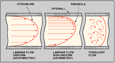
Figure
1: Laminar and turbulent flow are two types normally encountered
in liquid flow Measurement operations. Most applications
involve turbulent flow, with R values above 3000. Viscous
liquids usually exhibit laminar flow, with R values below
2000. The transition zone between the two levels may be
either laminar or turbulent.
|
The
equation is:
R
= 3160 x Q x Gt
D x µ
where:
R
= Reynolds number
Q
= liquid's flow rate, gpm
Gt
= liquid's specific gravity
D
= inside pipe diameter, in.
µ
= liquid's viscosity, cp
|
The
flow rate and the specific gravity are inertia forces, and
the pipe diameter and viscosity are drag forces. The pipe
diameter and the specific gravity remain constant for most
liquid applications. At very low velocities or high viscosities,
R is low, and the liquid flows in smooth layers with the
highest velocity at the center of the pipe and low velocities
at the pipe wall where the viscous forces restrain it. This
type of flow is called laminar flow. R values are below
approximately 2000. A characteristic of laminar flow is
the parabolic shape of its velocity profile, Fig. 1.
However,
most applications involve turbulent flow, with R values
above 3000. Turbulent flow occurs at high velocities or
low viscosities. The flow breaks up into turbulent eddies
that flow through the pipe with the same average velocity.
Fluid velocity is less significant, and the velocity profile
is much more uniform in shape. A transition zone exists
between turbulent and laminar flows. Depending on the piping
configuration and other installation conditions, the flow
may be either turbulent or laminar in this zone.
|
 |
FLOWMETER
TYPES
Numerous
types of flowmeters are available for closed-piping systems. In
general, the equipment can be classified as differential pressure,
positive displacement, velocity, and mass meters. Differential
pressure devices (also known as head meters) include orifices,
venturi tubes, flow tubes, flow nozzles, pitot tubes, elbow-tap
meters, target meters, and variable-area meters, Fig. 2.
Positive displacement meters include piston, oval-gear, nutating-disk,
and rotary-vane types. Velocity meters consist of turbine, vortex
shedding, electromagnetic, and sonic designs. Mass meters include
Coriolis and thermal types. The measurement of liquid flows in
open channels generally involves weirs and flumes.
Space limitations prevent a detailed discussion of all the liquid
flowmeters available today. However, summary characteristics of
common devices are shown in Table 1. (Click
here to see Table1) Brief descriptions follow.
Differential
Pressure Meters
The use of differential pressure as an inferred measurement of
a liquid's rate of flow is well known. Differential pressure flowmeters
are, by far, the most common units in use today. Estimates are
that over 50 percent of all liquid flow measurement applications
use this type of unit.
The
basic operating principle of differential pressure flowmeters
is based on the premise that the pressure drop across the meter
is proportional to the square of the flow rate. The flow rate
is obtained by measuring the pressure differential and extracting
the square root.
Differential
pressure flowmeters, like most flowmeters, have a primary and
secondary element. The primary element causes a change in kinetic
energy, which creates the differential pressure in the pipe. The
unit must be properly matched to the pipe size, flow conditions,
and the liquid's properties. And, the measurement accuracy of
the element must be good over a reasonable range. The secondary
element measures the differential pressure and provides the signal
or read-out that is converted to the actual flow value.
Orifices
are the most popular liquid flowmeters in use today. An orifice
is simply a flat piece of metal with a specific-sized hole bored
in it. Most orifices are of the concentric type, but eccentric,
conical (quadrant), and segmental designs are also available.
In
practice, the orifice plate is installed in the pipe between two
flanges. Acting as the primary device, the orifice constricts
the flow of liquid to produce a differential pressure across the
plate. Pressure taps on either side of the plate are used to detect
the difference. Major advantages of orifices are that they have
no moving parts and their cost does not increase significantly
with pipe size.
Conical
and quadrant orifices are relatively new. The units were developed
primarily to measure liquids with low Reynolds numbers. Essentially
constant flow coefficients can be maintained at R values below
5000. Conical orifice plates have an upstream bevel, the depth
and angle of which must be calculated and machined for each application.
The
segmental wedge is a variation of the segmental orifice. It is
a restriction orifice primarily designed to measure the flow of
liquids containing solids. The unit has the ability to measure
flows at low Reynolds numbers and still maintain the desired square-root
relationship. Its design is simple, and there is only one critical
dimension the wedge gap. Pressure drop through the unit is only
about half that of conventional orifices.
Integral
wedge assemblies combine the wedge element and pressure taps into
a one-piece pipe coupling bolted to a conventional pressure transmitter.
No special piping or fittings are needed to install the device
in a pipeline.
Metering
accuracy of all orifice flowmeters depends on the installation
conditions, the orifice area ratio, and the physical properties
of the liquid being measured.
Venturi
tubes have the advantage of being able to handle large flow
volumes at low pressure drops. A venturi tube is essentially a
section of pipe with a tapered entrance and a straight throat.
As liquid passes through the throat, its velocity increases, causing
a pressure differential between the inlet and outlet regions.
The flowmeters have no moving parts. They can be installed in
large diameter pipes using flanged, welded or threaded-end fittings.
Four or more pressure taps are usually installed with the unit
to average the measured pressure. Venturi tubes can be used with
most liquids, including those having a high solids content.
Flow
tubes are somewhat similar to venturi tubes except that they
do not have the entrance cone. They have a tapered throat, but
the exit is elongated and smooth. The distance between the front
face and the tip is approximately one-half the pipe diameter.
Pressure taps are located about one-half pipe diameter downstream
and one pipe diameter upstream.
Flow
Nozzles, at high velocities, can handle approximately 60 percent
greater liquid flow than orifice plates having the same pressure
drop. Liquids with suspended solids can also be metered. However,
use of the units is not recommended for highly viscous liquids
or those containing large amounts of sticky solids.
Pitot
tubes sense two pressures simultaneously, impact and static.
The impact unit consists of a tube with one end bent at right
angles toward the flow direction. The static tube's end is closed,
but a small slot is located in the side of the unit. The tubes
can be mounted separately in a pipe or combined in a single casing.
Pitot
tubes are generally installed by welding a coupling on a pipe
and inserting the probe through the coupling. Use of most pitot
tubes is limited to single point measurements. The units are susceptible
to plugging by foreign material in the liquid. Advantages of pitot
tubes are low cost, absence of moving parts, easy installation,
and minimum pressure drop.
Elbow
meters operate on the principle that when liquid travels in
a circular path, centrifugal force is exerted along the outer
edges. Thus, when liquid flows through a pipe elbow, the force
on the elbow's interior surface is proportional to the density
of the liquid times the square of its velocity. In addition, the
force is inversely proportional to the elbow's radius.
Any
90 deg. pipe elbow can serve as a liquid flowmeter. All that is
required is the placement of two small holes in the elbow's midpoint
(45 deg. point) for piezometer taps. Pressure-sensing lines can
be attached to the taps by using any convenient method.
Target
meters sense and measure forces caused by liquid impacting
on a target or drag-disk suspended in the liquid stream. A direct
indication of the liquid flow rate is achieved by measuring the
force exerted on the target. In its simplest form, the meter consists
only of a hinged, swinging plate that moves outward, along with
the liquid stream. In such cases, the device serves as a flow
indicator.
A more sophisticated version uses a precision, low-level force
transducer sensing element. The force of the target caused by
the liquid flow is sensed by a strain gage. The output signal
from the gage is indicative of the flow rate. Target meters are
useful for measuring flows of dirty or corrosive liquids.
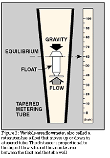 Variable-area
meters, often called variable area flow meters, consist essentially of a tapered
tube and a float, Fig. 3. Although classified as differential
pressure units, they are, in reality, constant differential pressure
devices. Flanged-end fittings provide an easy means for installing
them in pipes. When there is no liquid flow, the float rests freely
at the bottom of the tube. As liquid enters the bottom of the
tube, the float begins to rise. The position of the float varies
directly with the flow rate. Its exact position is at the point
where the differential pressure between the upper and lower surfaces
balance the weight of the float. Variable-area
meters, often called variable area flow meters, consist essentially of a tapered
tube and a float, Fig. 3. Although classified as differential
pressure units, they are, in reality, constant differential pressure
devices. Flanged-end fittings provide an easy means for installing
them in pipes. When there is no liquid flow, the float rests freely
at the bottom of the tube. As liquid enters the bottom of the
tube, the float begins to rise. The position of the float varies
directly with the flow rate. Its exact position is at the point
where the differential pressure between the upper and lower surfaces
balance the weight of the float.
Because
the flow rate can be read directly on a scale mounted next to
the tube, no secondary flow-reading devices are necessary. However,
if desired, automatic sensing devices can be used to sense the
float's level and transmit a flow signal. Variable Area Flow Meter tubes are
manufactured from glass, metal, or plastic. Tube diameters vary
from 1/4 to greater than 6 in.
Positive-Displacement
Meters
Operation
of these units consists of separating liquids into accurately
measured increments and moving them on. Each segment is counted
by a connecting register. Because every increment represents a
discrete volume, positive-displacement units are popular for automatic
batching and accounting applications. Positive-displacement meters
are good candidates for measuring the flows of viscous liquids
or for use where a simple mechanical meter system is needed.
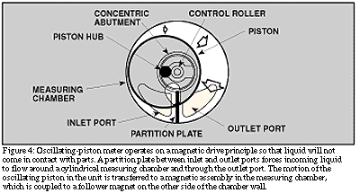
Reciprocating
piston meters are of the single and multiple-piston types.
The specific choice depends on the range of flow rates required
in the particular application. Piston meters can be used to handle
a wide variety of liquids. A magnetically driven, oscillating
piston meter is shown in Fig. 4. Liquid never comes in contact
with gears or other parts that might clog or corrode.
Oval-gear
meters have two rotating, oval-shaped gears with synchronized,
close fitting teeth. A fixed quantity of liquid passes through
the meter for each revolution. Shaft rotation can be monitored
to obtain specific flow rates.
Nutating-disk
meters have a moveable disk mounted on a concentric sphere
located in a spherical side-walled chamber. The pressure of the
liquid passing through the measuring chamber causes the disk to
rock in a circulating path without rotating about its own axis.
It is the only moving part in the measuring chamber.
A
pin extending perpendicularly from the disk is connected to a
mechanical counter that monitors the disk's rocking motions. Each
cycle is proportional to a specific quantity of flow. As is true
with all positive-displacement meters, viscosity variations below
a given threshold will affect measuring accuracies. Many sizes
and capacities are available. The units can be made from a wide
selection of construction materials.
Rotary-vane
meters are available in several designs, but they all operate
on the same principle. The basic unit consists of an equally divided,
rotating impeller (containing two or more compartments) mounted
inside the meter's housing. The impeller is in continuous contact
with the casing. A fixed volume of liquid is swept to the meter's
outlet from each compartment as the impeller rotates. The revolutions
of the impeller are counted and registered in volumetric units.
Helix
flowmeters consist of two radically pitched helical rotors geared
together, with a small clearance between the rotors and the casing.
The two rotors displace liquid axially from one end of the chamber
to the other.
Velocity
Meters
These
instruments operate linearly with respect to the volume flow rate.
Because there is no square-root relationship (as with differential
pressure devices), their rangeability is greater. Velocity meters
have minimum sensitivity to viscosity changes when used at Reynolds
numbers above 10,000. Most velocity-type meter housings are equipped
with flanges or fittings to permit them to be connected directly
into pipelines.
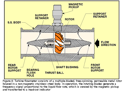
Turbine
meters have found widespread use for accurate liquid measurement
applications. The unit consists of a multiple-bladed rotor mounted
with a pipe, perpendicular to the liquid flow. The rotor spins
as the liquid passes through the blades. The rotational speed
is a direct function of flow rate and can be sensed by magnetic
pick-up, photoelectric cell, or gears. Electrical pulses can be
counted and totalized, Fig. 5.
The number of electrical pulses counted for a given period of
time is directly proportional to flow volume. A tachometer can
be added to measure the turbine's rotational speed and to determine
the liquid flow rate. Turbine meters, when properly specified
and installed, have good accuracy, particularly with low-viscosity
liquids.
A
major concern with turbine meters is bearing wear. A "bearingless"
design has been developed to avoid this problem. Liquid entering
the meter travels through the spiraling vanes of a stator that
imparts rotation to the liquid stream. The stream acts on a sphere,
causing it to orbit in the space between the first stator and
a similarly spiraled second stator. The orbiting movement of the
sphere is detected electronically. The frequency of the resulting
pulse output is proportional to flow rate.
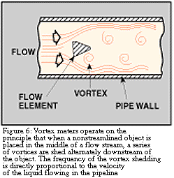 Vortex
meters make use of a natural phenomenon that occurs when a
liquid flows around a bluff object. Eddies or vortices are shed
alternately downstream of the object. The frequency of the vortex
shedding is directly proportional to the velocity of the liquid
flowing through the meter, Fig. 6. Vortex
meters make use of a natural phenomenon that occurs when a
liquid flows around a bluff object. Eddies or vortices are shed
alternately downstream of the object. The frequency of the vortex
shedding is directly proportional to the velocity of the liquid
flowing through the meter, Fig. 6.
The
three major components of the flowmeter are a bluff body strut-mounted
across the flowmeter bore, a sensor to detect the presence of
the vortex and to generate an electrical impulse, and a signal
amplification and conditioning transmitter whose output is proportional
to the flow rate, Fig. 7. The meter is equally suitable for flow
rate or flow totalization measurements. Use for slurries or high
viscosity liquids is not recommended.
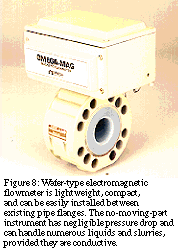
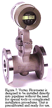 Electromagnetic
meters can handle most liquids and slurries, providing that
the material being metered is electrically conductive. Major components
are the flow tube (primary element), Fig. 8. The flow tube mounts
directly in the pipe. Pressure drop across the meter is the same
as it is through an equivalent length of pipe because there are
no moving parts or obstructions to the flow. The voltmeter can
be attached directly to the flow tube or can be mounted remotely
and connected to it by a shielded cable. Electromagnetic
meters can handle most liquids and slurries, providing that
the material being metered is electrically conductive. Major components
are the flow tube (primary element), Fig. 8. The flow tube mounts
directly in the pipe. Pressure drop across the meter is the same
as it is through an equivalent length of pipe because there are
no moving parts or obstructions to the flow. The voltmeter can
be attached directly to the flow tube or can be mounted remotely
and connected to it by a shielded cable.
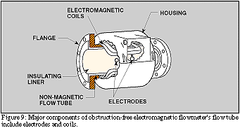
Electromagnetic flowmeters operate on Faraday's law of electromagnetic
induction that states that a voltage will be induced when a conductor
moves through a magnetic field. The liquid serves as the conductor;
the magnetic field is created by energized coils outside the flow
tube, Fig. 9. The amount of voltage produced is directly proportional
to the flow rate. Two electrodes mounted in the pipe wall detect
the voltage, which is measured by the secondary element.
Electromagnetic
flowmeters have major advantages: They can measure difficult and
corrosive liquids and slurries; and they can measure forward as
well as reverse flow with equal accuracy. Disadvantages of earlier
designs were high power consumption, and the need to obtain a
full pipe and no flow to initially set the meter to zero. Recent
improvements have eliminated these problems. Pulse-type excitation
techniques have reduced power consumption, because excitation
occurs only half the time in the unit. Zero settings are no longer
required.
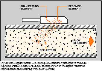
 Ultrasonic
flowmeters can be divided into Doppler meters and time-of-travel
(or transit) meters. Doppler meters measure the frequency shifts
caused by liquid flow. Two transducers are mounted in a case attached
to one side of the pipe. A signal of known frequency is sent into
the liquid to be measured. Solids, bubbles, or any discontinuity
in the liquid, cause the pulse to be reflected to the receiver
element, Fig. 10. Because the liquid causing the reflection is
moving, the frequency of the returned pulse is shifted. The frequency
shift is proportional to the liquid's velocity. Ultrasonic
flowmeters can be divided into Doppler meters and time-of-travel
(or transit) meters. Doppler meters measure the frequency shifts
caused by liquid flow. Two transducers are mounted in a case attached
to one side of the pipe. A signal of known frequency is sent into
the liquid to be measured. Solids, bubbles, or any discontinuity
in the liquid, cause the pulse to be reflected to the receiver
element, Fig. 10. Because the liquid causing the reflection is
moving, the frequency of the returned pulse is shifted. The frequency
shift is proportional to the liquid's velocity.
A
portable Doppler meter capable of being operated on AC power or
from a rechargeable power pack has recently been developed. The
sensing heads are simply clamped to the outside of the pipe, and
the instrument is ready to be used. Total weight, including the
case, is 22 lb. A set of 4 to 20 millampere output terminals permits
the unit to be connected to a strip chart recorder or other remote
device.
Time-of-travel
meters have transducers mounted on each side of the pipe. The
configuration is such that the sound waves traveling between the
devices are at a 45 deg. angle to the direction of liquid flow.
The speed of the signal traveling between the transducers increases
or decreases with the direction of transmission and the velocity
of the liquid being measured. A time-differential relationship
proportional to the flow can be obtained by transmitting the signal
alternately in both directions. A limitation of time-of-travel
meters is that the liquids being measured must be relatively free
of entrained gas or solids to minimize signal scattering and absorption.
Mass
Flowmeters The continuing need for more accurate flow measurements
in mass-related processes (chemical reactions, heat transfer,
etc.) has resulted in the development of mass flowmeters. Various
designs are available, but the one most commonly used for liquid
flow applications is the Coriolis meter. Its operation is based
on the natural phenomenon called the Coriolis force, hence the
name.
Coriolis
meters are true mass meters that measure the mass rate of
flow directly as opposed to volumetric flow. Because mass does
not change, the meter is linear without having to be adjusted
for variations in liquid properties. It also eliminates the need
to compensate for changing temperature and pressure conditions.
The meter is especially useful for measuring liquids whose viscosity
varies with velocity at given temperatures and pressures.
Coriolis meters are also available in various designs. A popular
unit consists of a U-shaped flow tube enclosed in a sensor housing
connected to an electronics unit. The sensing unit can be installed
directly into any process. The electronics unit can be located
up to 500 feet from the sensor.
Inside
the sensor housing, the U-shaped flow tube is vibrated at its
natural frequency by a magnetic device located at the bend of
the tube. The vibration is similar to that of a tuning fork, covering
less than 0.1 in. and completing a full cycle about 80 times/sec.
As the liquid flows through the tube, it is forced to take on
the vertical movement of the tube, Fig. 11. When the tube is moving
upward during half of its cycle, the liquid flowing into the meter
resists being forced up by pushing down on the tube.
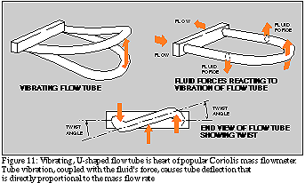
Having
been forced upward, the liquid flowing out of the meter resists
having its vertical motion decreased by pushing up on the tube.
This action causes the tube to twist. When the tube is moving
downward during the second half of its vibration cycle, it twists
in the opposite direction.
Having been forced upward, the liquid flowing out of the meter
resists having its vertical motion decreased by pushing up on
the tube. This action causes the tube to twist. When the tube
is moving downward during the second half of its vibration cycle,
it twists in the opposite direction. The ammount of twist is directly
proportional to the mass flow rate of the liquid flowing through
the tube. Magnetic sensors located on each side of the flow tube
measure the tube velocities, which change as the tube twists.
The sensors feed this information to the electronics unit, where
it is processed and converted to a voltage proportional to mass
flow rate. The meter has a wide range of applications from adhesives
and coatings to liquid nitrogen.
Thermal-type
mass flowmeters have traditionally been used for gas measurements,
but designs for liquid flow measurements are available. These
mass meters also operate independent of density, pressure, and
viscosity. Thermal meters use a heated sensing element isolated
from the fluid flow path. The flow stream conducts heat from the
sensing element. The conducted heat is directly proportional to
the mass flow rate. The sensor never comes into direct contact
with the liquid, Fig. 12. The electronics package includes the
flow analyzer, temperature compensator, and a signal conditioner
that provides a linear output directly proportional to mass flow.
 Open
Channel Meters Open
Channel Meters
The
"open channel" refers to any conduit in which liquid flows with
a free surface. Included are tunnels, nonpressurized sewers, partially
filled pipes, canals, streams, and rivers. Of the many techniques
available for monitoring open-channel flows, depth-related methods
are the most common. These techniques presume that the instantaneous
flow rate may be determined from a measurement of the water depth,
or head. Weirs and flumes are the oldest and most widely used
primary devices for measuring open-channel flows.
Weirs
operate on the principle that an obstruction in a channel will
cause water to back up, creating a high level (head) behind the
barrier. The head is a function of flow velocity, and, therefore,
the flow rate through the device. Weirs consist of vertical plates
with sharp crests. The top of the plate can be straight or notched.
Weirs are classified in accordance with the shape of the notch.
The basic types are V-notch, rectangular, and trapezoidal.
Flumes
are generally used when head loss must be kept to a minimum, or
if the flowing liquid contains large amounts of suspended solids.
Flumes are to open channels what venturi tubes are to closed pipes.
Popular flumes are the Parshall and Palmer-Bowlus designs.
The
Parshall flume consists of a converging upstream section, a throat,
and a diverging downstream section. Flume walls are vertical and
the floor of the throat is inclined downward. Head loss through
Parshall flumes is lower than for other types of open-channel
flow measuring devices. High flow velocities help make the flume
self-cleaning. Flow can be measured accurately under a wide range
of conditions.
Palmer-Bowlus
flumes have a trapezoidal throat of uniform cross section and
a length about equal to the diameter of the pipe in which it is
installed. It is comparable to a Parshall flume in accuracy and
in ability to pass debris without cleaning. A principal advantage
is the comparative ease with which it can be installed in existing
circular conduits, because a rectangular approach section is not
required.
Discharge
through weirs and flumes is a function of level, so level measurement
techniques must be used with the equipment to determine flow rates.
Staff gages and float-operated units are the simplest devices
used for this purpose. Various electronic sensing, totalizing,
and recording systems are also available.
A
more recent development consists of using ultrasonic pulses to
measure liquid levels. Measurements are made by sending sound
pulses from a sensor to the surface of the liquid, and timing
the echo return. Linearizing circuitry converts the height of
the liquid into flow rate. A strip chart recorder logs the flow
rate, and a digital totalizer registers the total gallons. Another
recently introduced microprocessor-based system uses either ultrasonic
or float sensors. A key-pad with an interactive liquid crystal
display simplifies programming, control, and calibration tasks.
SELECTING
A FLOWMETER
Experts
claim that over 75 percent of the flowmeters installed in industry
are not performing satisfactorily. And improper selection accounts
for 90 percent of these problems. Obviously, flowmeter selection
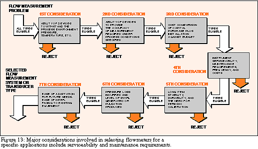
is no job for amateurs. The major steps involved in the selection
process are shown in Fig. 13.
The
most important requirement is knowing exactly what the instrument
is supposed to do. Here are some questions to consider. Is the
measurement for process control (where repeatability is the major
concern), or for accounting or custody transfer (where high accuracy
is important)? Is local indication or a remote signal required?
If a remote output is required, is it to be a proportional signal,
or a contact closure to start or stop another device? Is the liquid
viscous, clean, or a slurry? Is it electrically conductive? What
is its specific gravity or density? What flow rates are involved
in the application? What are the processes' operating temperatures
and pressures? Accuracy (see glossary), range, linearity, repeatability,
and piping requirements must also be considered.
It
is just as important to know what a flowmeter cannot do as well
as what it can do before a final selection is made. Each instrument
has advantages and disadvantages, and the degree of performance
satisfaction is directly related to how well an instrument's capabilities
and shortcomings are matched to the application's requirements.
Often, users have expectations of a flowmeter's performance that
are not consistent with what the supplier has provided. Most suppliers
are anxious to help customers pick the right flowmeter for a particular
job. Many provide questionnaires, checklists, and specification
sheets designed to obtain the critical information necessary to
match the correct flowmeter to the job.
Technological
improvements of flowmeters must be considered also. For example,
a common mistake is to select a design that was most popular for
a given application some years ago and to assume that it is still
the best instrument for the job. Many changes and innovations
may have occurred in recent years in the development of flowmeters
for that particular application, making the choice much broader.
A recent development is the availability of computer programs
to perform the tedious calculations often necessary for selecting
flowmeters. Calculations that used to take an hour can be performed
in a matter of seconds (see accompanying section, "Selected Reference
Material").
Click
Here For Questions To Ask When Selecting A Flowmeter
Cost
Considerations
There are a wide range of prices for flowmeters. Variable Area Flow Meters are
usually the least expensive, with some small-sized units available
for less than $100. Mass flowmeters cost the most. Prices start
at about $3500. However, total system costs must always be considered
when selecting flowmeters. For example, an orifice plate may cost
only about $50. But the transmitter may add an additional $500
or $600, and sensing line fabrication and installation may cost
even more.
Installation,
operation, and maintenance costs are important economic factors
too. Servicing can be expensive on some of the more complicated
designs.
As
with many other products, a plant engineer generally gets what
he pays for when he purchases a flowmeter. But the satisfaction
that he receives with the product will depend on the care that
he uses in selecting and installing the instrument. And that gets
back to knowing the process, the products, and the flow-metering
requirements. "Overbuying" is not uncommon. Plant engineers should
not buy a flowmeter more capable or complicated than they need.
WORKING
WITH FLOWMETERS
Although
suppliers are always ready to provide flowmeter installation service,
estimates are that approximately 75 percent of the users install
their own equipment. But installation mistakes are made. One of
the most common is not allowing sufficient upstream and downstream
straight-run piping for the flowmeter.
Every design has a certain amount of tolerance to nonstable velocity
conditions in the pipe, but all units require proper piping configurations
to operate efficiently. Proper piping provides a normal flow pattern
for the device. Without it, accuracy and performance are adversely
affected. Flowmeters are also installed backwards on occasion
(especially true with orifice plates). Pressure-sensing lines
may be reversed too.
With
electrical components, intrinsic safety is an important consideration
in hazardous areas. Most flowmeter suppliers offer intrinsically
safe designs for such uses.
Stray
magnetic fields exist in most industrial plants. Power lines,
relays, solenoids, transformers, motors, and generators all contribute
their share of interference. Users must ensure themselves that
the flowmeter they have selected is immune to such interference.
Problems occur primarily with the electronic components in secondary
elements, which must be protected. Strict adherence to the manufacturer's
recommended installation practices will usually prevent such problems.
Calibration
All
flowmeters require an initial calibration. Most of the time, the
instrument is calibrated by the manufacturer for the specified
service conditions. However, if qualified personnel are available
in the plant, the user can perform his own calibrations.
The
need to recalibrate depends to a great extent on how well the
meter fits the application. Some liquids passing through flowmeters
tend to be abrasive, erosive, or corrosive. In time, portions
of the device will deteriorate sufficiently to affect performance.
Some designs are more susceptible to damage than others. For example,
wear of individual turbine blades will cause performance changes.
If the application is critical, flowmeter accuracy should be checked
at frequent intervals. In other cases, recalibration may not be
necessary for years because the application is noncritical, or
nothing will change the meter's performance. Some flowmeters require
special equipment for calibration. Most manufacturers will provide
such service in their plant or in the user's facility, where they
will bring the equipment for on-site calibration.
Maintenance
A
number of factors influence maintenance requirements and the life
expectancy of flowmeters. The major factor, of course, is matching
the right instrument to the particular application. Poorly selected
devices invariably will cause problems at an early date. Flowmeters
with no moving parts usually will require less attention than
units with moving parts. But all flowmeters eventually require
some kind of maintenance.
Primary elements in differential pressure flowmeters require extensive
piping, valves, and fittings when they are connected to their
secondary elements, so maintenance may be a recurring effort in
such installations. Impulse lines can plug or corrode and have
to be cleaned or replaced. And, improper location of the secondary
element can result in measurement errors. Relocating the element
can be expensive.
Flowmeters
with moving parts require periodic internal inspection, especially
if the liquid being metered is dirty or viscous. Installing filters
ahead of such units will help minimize fouling and wear. Obstructionless
instruments, such as ultrasonic or electromagnetic meters, may
develop problems with their secondary element's electronic components.
Pressure sensors associated with secondary elements should be
periodically removed and inspected.
Applications where coatings may occur are also potential problems
for obstructionless instruments such as magnetic or ultrasonic
units. If the coating is insulating, the operation of magnetic
flowmeters will ultimately be impaired if the electrodes are insulated
from the liquid. This condition will be prevented by periodic
cleaning. With ultrasonic flowmeters, refraction angles may change
and the sonic energy absorbed by the coating will cause the meter
to become inoperative.
Reprinted
with permission from Plant Engineering Magazine,November 21, 1984.
© by Cahners Publishing Company.
| 


